I recently did a presentation for the MN Amateur Radio Technical Society (MN-ARTS) on Operational Amplifiers. During that presentation, I was showing and discussing some of the applications in ham radio for Op Amps and one of them involved the use within SDR’s to perform a Hilbert Transform on the sampled RF in order to pass this onto a DSP function using the PC sound card audio approach used in 1st and 2nd generation SDRs. That prompted a side conversation on the possibility of doing an SDR kit for our November Build-A-Thon.
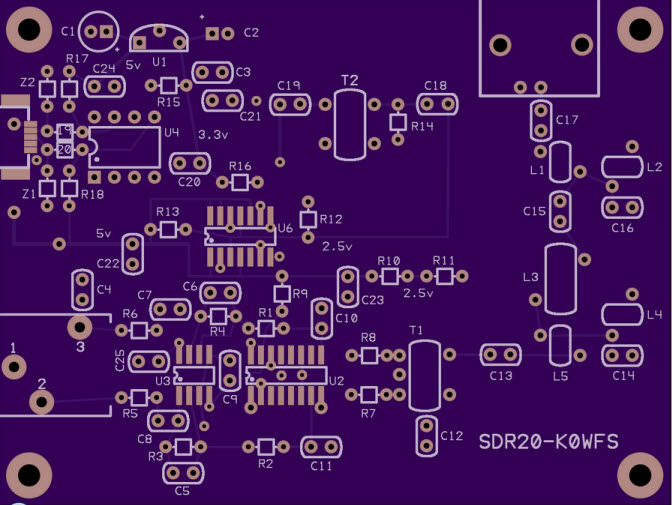
So I went off to see what I could put together for a minimal SDR kit. Surveying the past and current designs, I came back to the Softrock series of SDR kits once I understood the implications of doing a hardware design that would work with existing SDR software packages like HDSDR, PowerSDR 2.4, SDR#, etc. As the Softrock series by Tony Parks, KB9YIG had been around for a while, I started thinking about simplifying and improving its design in order to reduce the BOM cost and at that same time provide a very functional kit. Below is the 1st board layout that I sent to OSHPark for prototyping.

SDR20 PCB layout
Some of the key changes I made were to use a mini USB-B instead of the bulky full size B connector, powering the entire board from USB, using a SN74CBT3253 analog switch IC, and adding a 5th order Butterworth front-end bandpass filter. One of the reasons the board can be run on USB power alone is that I used lower power components and went with a single-band design rather than a multi-band approach. As this kit was intended to be simpler, and less costly than a Softrock Ensemble for example, a single-band receiver was a good way to reduce the BOM.
One major challenge in reducing the area of the PCB, again to reduce cost, was in the layout while attempting to keep the digital traces away from the analog to reduce spur generation from the broadband nature of the 4x and 1x signals within the digital circuits.
The boards from OSHPark came in Thursday’s mail and I planned a Saturday morning of fun-filled soldering. My main goal was to get the kit assembled to see if I had actually pulled-off a correct layout in 1 rev. Fortunately I had, though I did manage to get the 3.3v LDO regulator symbol backwards on the PCB silkscreen. I’ll take that kind of PCB layout error anyday over cutting traces and adding blue wires. So I was happy to see and hear CW signals when I first put the board into service with HDSDR.
Below is the populated PCB, with an SI570 on the bottom layer near the ATTINY-85 micro sitting in the 8-pin DIP socket.
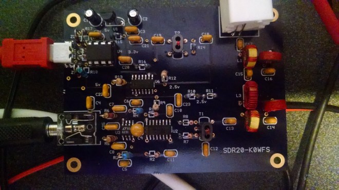
Built-out SDR20 board
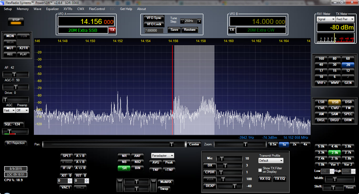
I prefer to use PowerSDR 2.4.4, just I had with the Softrock I built about 2 years ago, primarily due to it’s superior DSP software capabilities and clean sound. Below is a capture of a QSO on 14.156 I was listening to this morning.

QSO on 14.156
The noise level was running about S-6 and one of the hams was running a FlexRadio SDR himself which had outstanding audio on TX, and I was able to widen the IF to 2.9 kHz and enjoy a crystal clear morning QSO.
More to come as I make a few minor revisions to the board and write-up the build instructions.
73


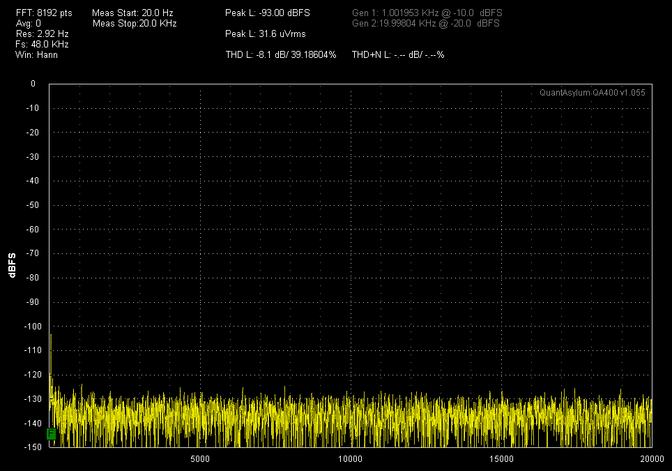
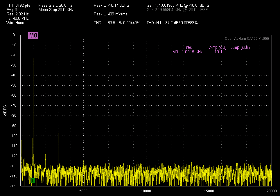


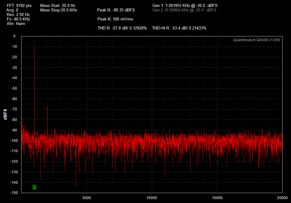
 As you can see above, the THD is exceeding spec and the THD+N at 0.002% is exceeding its spec of 0.0038%, both at an input level of -10 dBFS. You will also note that the noise floor of a QA400 sits at about -140 dBFS.